Proton Exchange Membrane (PEM) cooling circuit

Advanced polymer cooling solutions for efficient heat management for PEM fuel cells.

Application

Cool Power: Polymer Solutions for Optimal PEM Fuel Cell Performance

In Proton-Exchange-Membrane fuel cells, managing the heat generated from hydrogen and oxygen reactions is vital to prevent overheating, as these cells typically operate at around 80ºC. Effective cooling strategies, such as air or liquid cooling with water or glycol-water blends, are essential to maintain optimal operating temperatures.

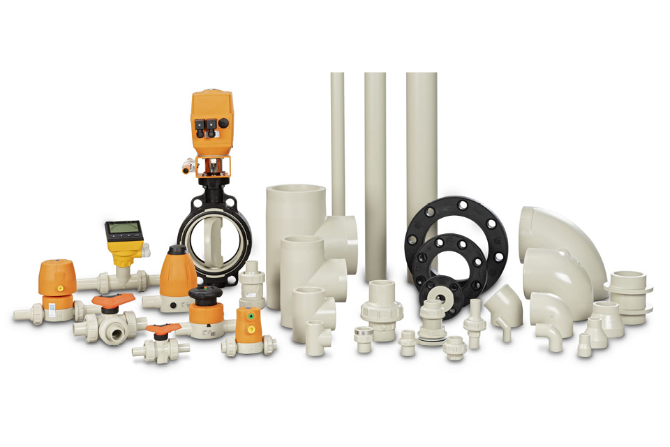
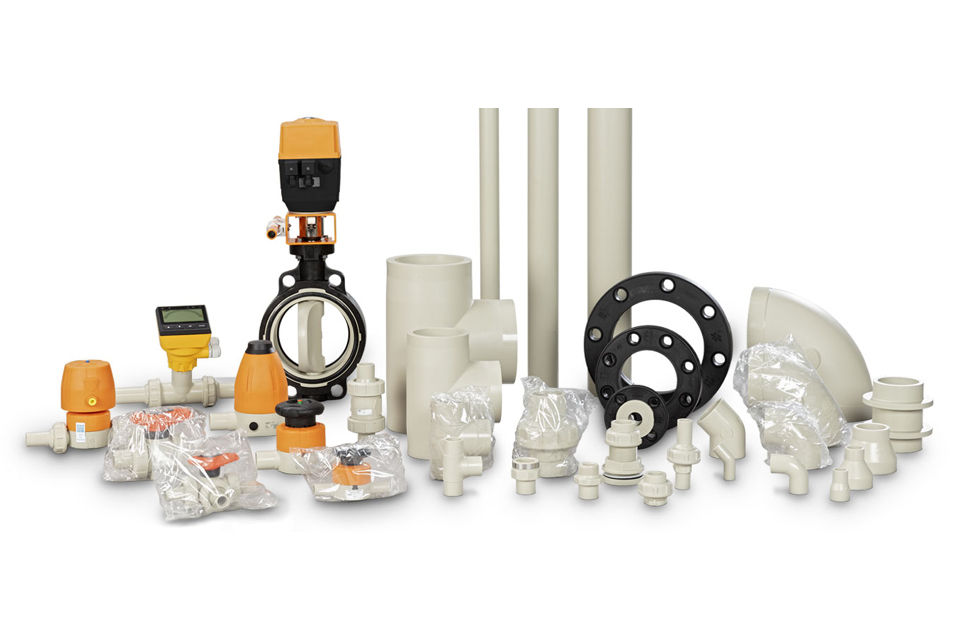
Polymer piping systems like our polypropylene piping solution PROGEF, play a critical role in this process. They offer the following benefits:

  • Efficient Heat Dissipation: The polypropylene (PP) welded system handles air and liquid cooling well, effectively removing excess heat to keep the fuel cell at its ideal temperature.
  • Durability and Compatibility: PP is suited for fuel cell cooling demands due to its robustness and compatibility with various thermal conditions.
  • Flexible Cooling Options: Our polypropylene (PP) welded system can handle different cooling media to effectively regulate and dissipate heat, ensuring the fuel cell's performance remains steady.

FAQs

How does a Proton Exchange Membrane (PEM) fuel cell operate, and what are its primary applications?

A Proton Exchange Membrane (PEM) fuel cell generates electricity through the electrochemical reaction of hydrogen and oxygen. Hydrogen at the anode splits into protons and electrons. The protons move through the polymer electrolyte membrane to the cathode, while the electrons create an electric current through an external circuit. At the cathode, protons, electrons, and oxygen combine to produce water as a byproduct.

PEM fuel cells are commonly used in transportation (e.g., fuel cell vehicles), stationary power generation, and portable power. Their adoption has increased due to the push for cleaner energy solutions, particularly in the marine and energy sectors. GF Piping Systems plays a crucial role in providing the necessary infrastructure for these applications. For more information on GF’s efforts to decarbonize these sectors, and our additional solution portfolio please visit our Marine industry page or our Energy industry page.

What is the role of polymer piping systems in PEM fuel cells, and how do they support system performance and sustainability?

Incorporating polymer piping systems plays a critical role in the operation of PEM fuel cells by facilitating the transportation of gases and liquids within the system. These systems offer a range of advantages over traditional metal piping, including resistance to corrosion, reduced ion leaching, and a lighter weight.

Moreover, by upholding the purity of the reactants and minimizing contamination, polymer piping systems effectively enhance the overall efficiency and longevity of PEM fuel cells. Furthermore, their durability significantly contributes to fuel cell systems' sustainability.

What are generally considered the best operating pressures for Proton Exchange Membrane (PEM) fuel cells, and how important might cooling be for their efficiency?

PEM fuel cells typically operate from near ambient pressure up to about 6 atm. Higher pressures can increase power density but may impact system efficiency due to the extra power needed for air compression.

  • Importance of Cooling: Effective cooling is crucial for maintaining the performance and lifespan of PEM fuel cells. The electrochemical reactions generate heat that must be managed to avoid overheating. Excessive temperatures can degrade the membrane and other critical components, reducing efficiency and lifespan.
  • Components Requiring Cooling: Key cooling components include the membrane electrode assembly (MEA), bipolar plates, and gas diffusion layers, which are sensitive to temperature variations.
  • Cooling Media: Common cooling media include water and glycol-water mixtures. These fluids circulate through the system to absorb and dissipate heat, keeping temperatures within the desired range.

Polymer piping systems are essential for heat management in PEM fuel cells, offering advantages like corrosion resistance, thermal insulation, flexibility, and compatibility with various cooling media. These benefits enhance the performance and sustainability of PEM fuel cells under different operating conditions.

Why is the polypropylene piping solution PROGEF a possible choice for cooling loops?

Polypropylene (PP) piping systems are widely utilized in cooling loops due to their superior material properties, offering several distinct advantages:

  • Corrosion resistance: PP exhibits excellent resistance to a broad range of chemicals and substances commonly present in cooling systems, such as water, glycol solutions, and mild acids. This resistance prevents corrosion and significantly extends the lifespan of the piping system.
  • Lightweight and easy Installation: PP piping components are much lighter than traditional metal ones, which simplifies handling and installation. This leads to reduced labor costs and shorter installation times, enhancing overall project efficiency.
  • Superior thermal insulation: The inherent thermal insulation properties of PP help to minimize heat loss or gain within the cooling loop, thereby improving the system's overall efficiency and performance.
  • Cost-effective solution: Compared to many other piping materials, PP is more cost-effective, making it an economically viable option for a variety of cooling applications without compromising on performance or durability.

These attributes make our polypropylene welded system PROGEF an ideal choice for cooling loops, providing a reliable, efficient, and economical solution for various industrial and commercial applications.

Learn more about our PROGEF polypropylene welded system.

Where can you find the pressure and temperature (pT) diagram of the polypropylene piping solution PROGEF to determine the working area?

To determine the working area of polypropylene (PP) welded systems, (PROGEF) it is essential to reference the pressure and temperature (pT) diagram. This diagram is a critical tool for engineers and system designers as it provides detailed information on the operating limits of the material under various pressure and temperature conditions.

The pT diagram for our PROGEF brand outlines the maximum allowable operating pressure for the material at different temperatures. By consulting this diagram, users can ensure that their system design stays within safe operational limits, thus preventing potential material failures and ensuring long-term reliability and efficiency.

To access the systems’ pT diagram, please visit our online tools page.: Pressure/Temperature Diagrams

Would you like to know more?

Click here to schedule a consultation with one of our experts and discuss your project requirements or any further questions you may have.

Georg Fischer Co. Ltd.

Sec 2, Guang Fu Rd.

241 New Taipei City

Taiwan

GF logo on the headquarters building